Understanding Thermal Forces in Rail
FIGURE 1. Photograph of a bright June sun. Summer heat and winter cold can induce forces in railroad rail large enough to cause track failures. (Courtesy of Gary T. Fry.)
RAILWAY AGE, JULY 2022 ISSUE: How temperature variations can cause sun kinks and pull-aparts
Welcome to “Timeout for Tech with Gary T. Fry, Ph.D., P.E.” Each month in this series, we examine a technology topic that professionals in the railway industry have asked to learn more about. This month we discuss how temperature variations can cause forces in railroad rail, even when trains are not present.
Figure 1 (above) is a photograph of the sun on a bright day in June. How is it that the heat of a summer day can cause several yards of railroad track to suddenly shift sideways out of alignment by a couple feet or more? Conversely, why does a rail suddenly snap in two on a cold winter day? Several scientific principles are in play to answer these questions, but one stands out as the most significant. Rail steel, like most metal materials, expands when heated and contracts when cooled.
There’s a fun way to think about this phenomenon. Being connected by rail lines, shouldn’t Chicago Union Station and St. Louis Union Station be pulled closer to one another in the winter and pushed farther apart in the summer? For example, over the 260-mile distance between the two stations (as the crow flies), rail laid stress-free at 65-degrees Fahrenheit will be 310 feet longer on a 100-degree summer afternoon and 490 feet shorter on a 10-degree winter night. That’s a swing of 800 feet! Setting amusement aside, what really happens?

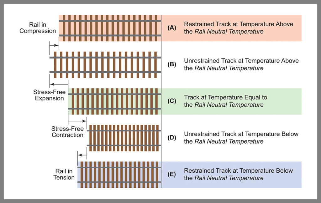
When rail is subjected to temperature variations, it moves relative to the ground surface. But it does not move freely because it is connected to ties that are buried in ballast. Let’s look at this more closely. Figure 2 shows five schematic drawings of the same short segment of track. In the drawings, the rail is attached to the ties in such a way that the rail and ties move exactly together. Drawing C, shaded green, illustrates the track segment at its natural, unstressed length: that is, at its rail neutral temperature or RNT. Drawing B shows the segment at its freely expanded, unrestrained length associated with some temperature above its RNT. Drawing D shows the segment at its freely contracted, unrestrained length associated with some temperature below its RNT. When considering drawings B and D, we should imagine that the track segment is not installed in ballast, rather the bottoms of the ties rest upon a frictionless surface. This allows the steel rail to assume the length it would naturally have at the given temperatures above or below its RNT. Stated another way, drawings B and D show the rail “where it wants to be” at those temperatures—longer and stress-free when heated or shorter and stress-free when cooled.
Now consider that the ties are confined within consolidated ballast, and, by various means, the rail is attached to the ties. Consequently, the rail cannot be “where it wants to be.” Drawing A, shaded red in Figure 2, shows where the rail winds up being at a given temperature above its RNT. The rail is held shorter than “where it wants to be” by some amount that depends upon the movement between the ties and ballast and the movement between the rail and the ties. It is being restrained and experiences axial compressive force as a result. Hence an axial compression force demand is being placed on the track structure because of the increase in temperature.
Drawing E, shaded blue in Figure 2, shows where the rail winds up being at a given temperature below its RNT. The rail is held longer than “where it wants to be” by some amount that similarly depends upon the movement between the ties and ballast and the movement between the rail and the ties. It is being restrained and experiences axial tensile force as a result. This time, an axial tension force demand is being placed on the track structure.
Those are the essential features through which temperature variations can cause axial compression and axial tension force demands in railroad rail. But we are just scratching the surface with that introduction. The specific magnitudes of rail forces that develop depend upon several details, many of which can exhibit substantial variability: for example, track type (jointed rail or continuously welded rail), rail size, rail neutral temperature, rail temperature (as opposed to ambient temperature), track geometry, proximity to special trackwork, proximity to a bridge, proximity to a grade crossing, rail anchorage arrangements, ballast condition, tie and fastener type and condition, etc. In combination, these details, their complex interactions, and their inherent variability, make it difficult to predict thermal forces in rail accurately and precisely.
Our discussion to this point has focused on the demand placed on the track structure because of rail temperature variation: that is, axial compression forces and axial tension forces. As a structural system, railroad track has capacity to resist these demands, but if the axial compression demand placed on the track exceeds its axial compression capacity, the track will likely experience failure in the form of an instability called buckling. The physical appearance of a track buckle is a significant lateral shift out of alignment. This failure mode is commonly termed a “sun kink,” because it happens most frequently on hot, sunny days, and it looks a bit like a kink in the rail when viewed from above.
Railroad track also has a finite capacity to resist axial tension. If its axial tension capacity is exceeded, the rail will break. This failure mode is commonly termed a “pull-apart,” because the tension in the rail results in formation of a gap between the broken rail ends, giving an appearance that the ends were pulled apart. Of special concern, if a rail contains a fatigue defect, its axial tension capacity is reduced and also becomes temperature dependent, being lower at lower temperatures. Hence, for rail with fatigue defects, cold weather brings the compounding effects of increased demand and reduced capacity. Rail that does not contain fatigue defects has negligible risk of failure, even under the most severe thermal tension forces that can be associated with winter conditions.
There are several options available to mitigate risk of failure associated with thermal forces in rail. For example, it is possible to adjust the RNT of rail. In the summer when the rail “wants to be longer,” sections of rail can be removed, shortening the rail, increasing the RNT, and lowering the compression forces. Conversely, RNT can be lowered for winter conditions by adding sections to the contracting rail, thereby reducing axial tension forces. Done strategically, RNT management can have the effect of reducing peak seasonal demands.

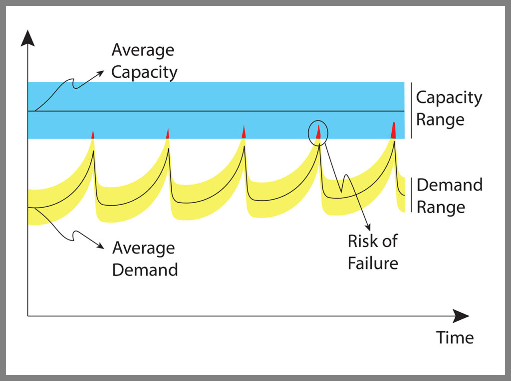
Figure 3 is a schematic diagram illustrating the effect of adjusting RNT to control seasonal demand. The blue region in Figure 3 represents capacity as a range around a central average value. It is assumed that the capacity of the rail does not change over the period represented. The yellow region represents demand as a range with a central average value. Periodic reductions in demand are indicated where RNT adjustments are made. Red markers indicate times when failure is likely: that is, when the upper reaches of demand exceed the lower reaches of capacity. Adjusting RNT is currently the most common method of mitigating sun kinks and pull-aparts. This would be considered an example of demand control to mitigate risk.
Although demand management can be an effective approach to mitigate risk of failure, it is also possible to increase capacity through relevant design, construction and maintenance procedures. Theoretically, if the safe design compression capacity of track to resist sun kinks can be increased adequately, the need for seasonal RNT adjustments could be nearly eliminated, while simultaneously decreasing risk of failure from sun kinks and pull-aparts. This would be considered a capacity control risk management approach.
In summary, sun kinks and pull-aparts are track failure modes associated with thermal forces that can develop in rail: axial compression and axial tension forces, respectively. The risk of these failures can be mitigated through demand management by adjusting rail neutral temperature. The failure risk can also be mitigated through capacity management, optimally by adequate increases to the axial compression capacity of the track system.
Dr. Fry is Vice President of Fry Technical Services, Inc. (https://www.frytechservices.com). He has 30 years of experience in research and consulting on the fatigue and fracture behavior of structural metals and weldments. His research results have been incorporated into international codes of practice used in the design of structural components and systems including structural welds, railway and highway bridges, and high-rise commercial buildings in seismic risk zones. He has extensive experience performing in situ testing of railway bridges under live loading of trains, including high-speed passenger trains and heavy-axle-load freight trains. His research, publications and consulting have advanced the state of the art in structural health monitoring and structural impairment detection.

No comments:
Post a Comment